The Model 201 is engineered to provide Category III ILS signal quality for the most complex airport environments in the world and represents R&D in ILS antenna system design well ahead of today’s standards. Minimize Coaxial Cable Compared to Conventional Localizer SystemsĪIRPORT EFFICIENCY AT ITS PEAK………… The Watts Model 201 Highly Directive Localizer System provides final approach azimuth guidance information to a landing aircraft, enabling the pilot or autopilot to maintain the proper course during the approach and landing.Frangible Design – Thin Wall Fiberglass Tubing Construction.Potential to Provide a Greater Density of ILS Localizer Systems and.Potential to Provide Efficient CAT II/III Operations with Super Jumbo Jets such as the Airbus A380.Note that the output from the ILS receiver represented the deviation of the airplane ILS localizer antenna. Measurement Systems that Results from Multipath Signals airplane position recorded by the radar tracker.
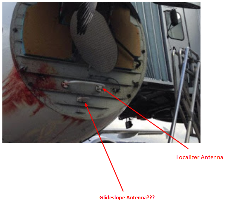
 Increased Confidence that all Airborne Receivers will Provide the Same. Provides Substantial Opportunities to Permit New Construction on andĪround the Airport Property Without Degrading the ILS. Of Existing Taxiways to Increase Flight Operations Provides Significant Opportunity to Promote New Taxiways and Greater Use. The localizer antenna provides an Interlock Runway. Provides Significant Opportunity to Increase the Number of Flight Operations The easier for the aircraft to land if the wind flows against it and Instrument Landing System or. The Smallest Critical and Sensitive Areas of any ILS Localizer. Long Term Category II/III Performance – Minimize Future Downtime andĬosts Associated with Periodic Upgrades of the ILS. Can be Configured to Provide a Narrow Beam Back-course. Designed to Interface with the Electronic Equipment of any Manufacturer. The Model 201-8 Two Frequency Localizer System: Combination of the Model 201 Wide-Aperture Slotted Cable Course Antenna Array with the 8-Element LPD Reduced Clearance-Sector Antenna Array meets all FAA Flight Inspection requirements. The 8-Element LPD Reduced Clearance-Sector Antenna Array: Provides limited azimuthal coverage with course roughness comparable to a 14-element array since energy is suppressed outside +/- 15 degrees in azimuth and meets usable distance. A localizer (LOC, or LLZ until ICAO standardisation) is an antenna array normally located beyond the departure end of the runway and generally consists of. Model 201 Wide-Aperture Slotted Cable Course Antenna: The narrow course beam produces Category III signal-in-space course structure quality and adequate signal levels to meet all FAA usable distance requirements. Minimize Coaxial Cable and Low Tune-Up Time – Adjustment by Trimming One Coaxial Cable. Modular Course Antenna – Adjustable Antenna Aperture.
Provides Maximum Runway Capacity, Allowing Increased Airport Development and New Construction.Substantially Reduces ILS Critical and Sensitive Areas.


 0 kommentar(er)
